Thursday, September 21, 2017

The Dolores Feed and Flour Mill

I recently purchased a kit for the Dolores Feed and Flour Mill produced by Narrow Gauge Colorado.  I have completed its construction, and wanted to share my experience regarding it construction, fit of parts, and instructions.

The kit consists of laser-cut parts that fit together perfectly.  The kit consists of laser-board sub walls, to which one glues the laser cut (perhaps laser-sculpted would be a better descriptor) corrugated siding.  The roof stacks appear to be 3-D printed parts, and fit into the pre-cut holes in the roof panels perfectly.  Kudos to the individual who did the laser cutting and 3-D printing.

 Because the instructions are rather short on detail, I have put together the following assembly sequence which I used to assemble this kit.  Follow along as I describe how I completed the Feed and Flour Mill.

1.  Assemble the subwalls, ensuring that the parts are aligned accurately.  I assembled the walls using Loctite thin ACC for the entire project.
2.  Paint the doors, assemble them, and glue to the backs of the subwalls, centering them in the openings.  I painted the doors using Rust-O-Leum's Clean Metal Primer, which is a nice white color.  I aligned the doors in their openings such that a space was left at the bottom to allow for the sills.
3.  Glue the floor and subfloor together, again using the Loctite ACC.  Ensure that the round holes in the floor are in alignment.
4.  Glue the back subwall to the base, ensuring that it is square to the base.
5.  Glue the second floor to the rear subwall, ensuring that it is square to the subwall.
6.  Glue the two-story gable subwall to the floor, second floor, and rear subwall.
7.  Glue the interior two-story gable subwall to the floor, second floor, and rear subwall.
8.  Glue the single-story gable subwall to the floor, and rear subwall.
9.  Glue the front subwall to the floor, second floor, and all three gable subwalls.
10.  Paint the siding and the roof your favorite shade of silver to represent galvanized metal.  I used Star-brand Smokebox Silver for the walls, and Floquil Platinum Mist for the roof panels.
11.  When thoroughly dry, mask the walls using blue painter's tape, exposing the windows and door trim.  These details are laser-cut into the corrugated siding.  I painted the windows and doors with Model Master White.
12.  Add the glazing to the windows using Canopy Glue.  Note that the glazing is to be installed on the outside and inside of the of the subwalls.  Recessed areas are laser-cut into the front surface of the subwalls to receive the glazing.

13.  Glue the front and rear siding to the subwalls, using Loctite ACC.  Then glue the two ends to the assembly, also using Loctite ACC.
15.  Install all roof rafters, and rafter tails into the slots in the completed walls.
16.  Add the subroof panels to the single-story portion of the structure ONLY.
17.  Glue the final piece of siding to the gable subwall above the subroof panel, using the Loctite ACC.
18.  Add the subroof panels to the two-story portion of the structure, again using the Loctite ACC.
19.  Add the notched rafters and barge boards to the roof, and paint them the trim color.
20.  Pre-paint the window sills the trim color, and install all window and door sills.
21.  Add the corrugated roof panels to the subroof.  I used Aleene's Tacky Glue to allow positioning.
22.  Add the corrugated ridge strips to the roofs.
23.  I weathered the Mill with Pan Pastels.  I used the following colors to achieve a rusty, weathered appearance:  Neutral Gray Shade; Burnt Sienna Shade; and Red Iron Oxide.
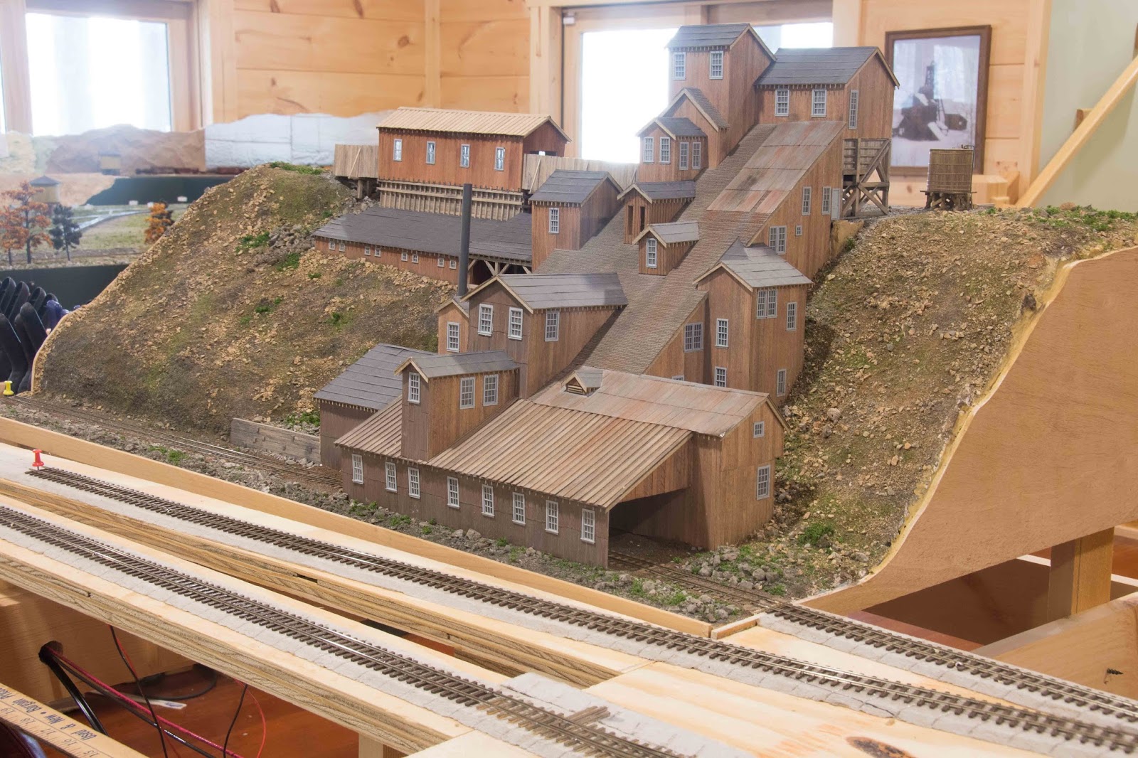
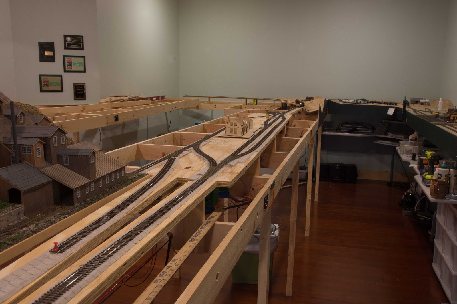
24.  I installed the structure in my town of Dolores, where it is ready to receive shipments!


The Dolores Feed Mill showing the painted and installed doors.

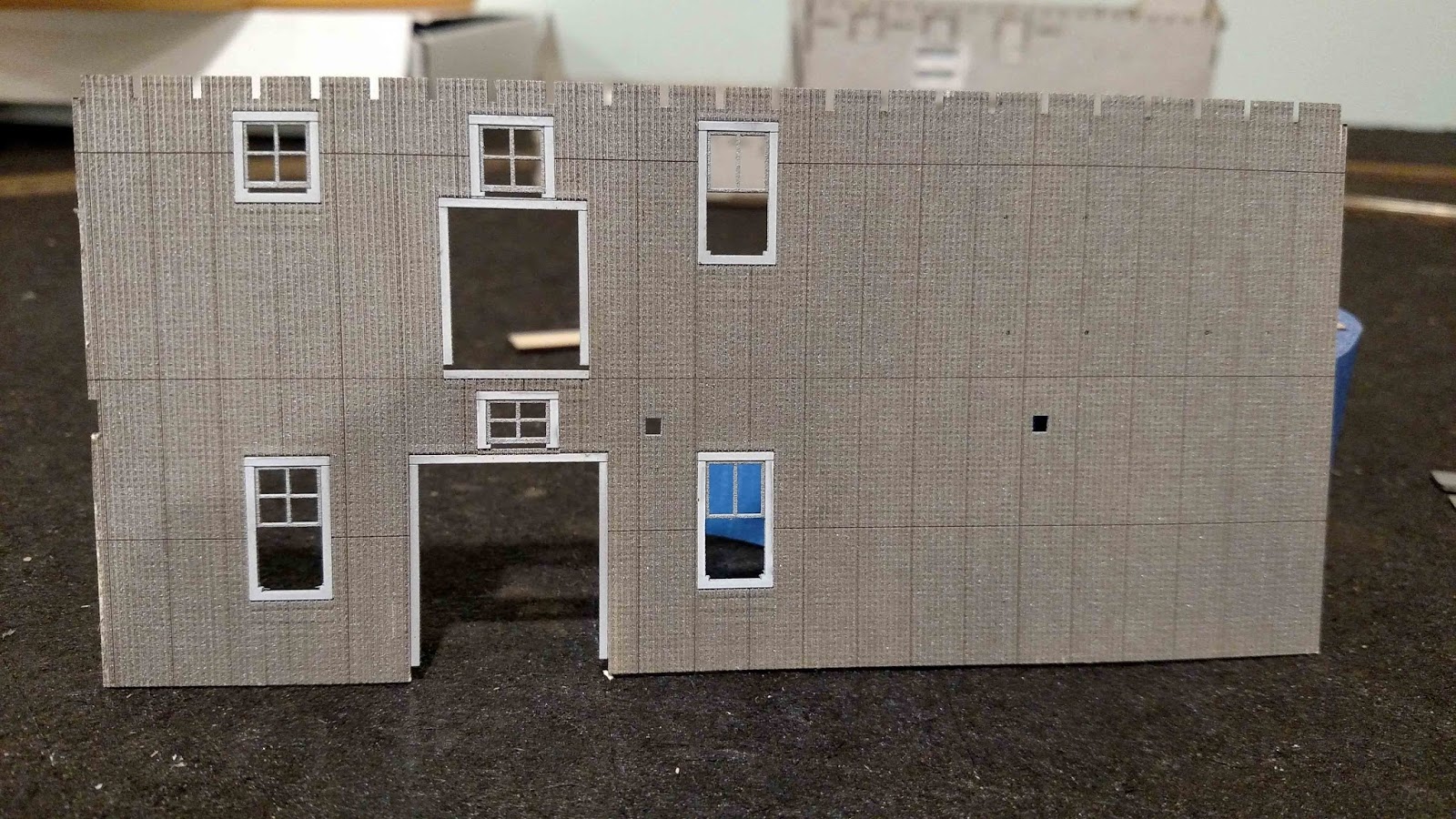
The front two-story wall of the Dolores Feed Mill, showing the fine laser-cut corrugations.  Note the Painted window and door trim.


The completed Dolores Feed Mill, prior to weathering.

Another view of the completed Dolores Feed Mill prior to weathering.

Three-quarter view of the Mill, showing the laser-cut wood end wall.

The rear of the Dolores Feed Mill.

The Dolores Feed and Flour Mill in place on the layout.

Wednesday, June 14, 2017

Operations on the Rio Grande Southern

Now that trackwork has been completed from Durango though Rico to Ophir, I have begun to host operating sessions on the railroad.  While the first two sessions were a "shakedown cruise" for the railroad, I decided that for the latest session I would initiate a trial operating session using card cards and waybills.  I used this system on my previous layout, and liked it.

In this session, I simply recycled the car cards and waybills from the old layout, and made some minor changes to adapt them to the current layout.  I also needed a place to store the car cards, so I made car card boxes and attached them to the fascia in each location where switching was to occur.  I made the car card boxes from nominal 1/4" lauan plywood.  Similar boxes are commercially available from Micro-Mark, but I wanted to customize the sizes to fit my operating scheme.

The following photos illustrate the basic construction of these boxes.  The boxes will be painted green to match the color of my fascia.


These are the parts required to construct a single box, with a coupler pick holder on one side.  The back is 3 1/2" tall, by 2 1/4" wide; the front is 1 3/4" by 2 1/4".  the bottom and side pieces are each 1/2" wide, with the bottom being 2/14" long.  The two side pieces are cut to fit, but will be approximately 1 1/2" tall.


These are the parts for a double box.  The parts are all the same size as for the single box, but are 4 1/2" long.


This is a completed triple box.  This box is 7 3/4" wide.  The attached coupler pick holder is approximately 1" square:  I cut it on my table saw to exactly match the thickness of the completed box.

Monday, March 27, 2017

Spline roadbed

I am starting the trackwork to Ophir following the completion of trackwork in Rico.  I am trying out a new technique to make the spline roadbed.  This was suggested to me via email from Steve Hatch, of Railway Engineering.  This method is faster to construct, and I find that it is easier for me to keep the splines and blocks aligned crossways than in the method I used before.

As before, I cut splines from scrap lauan plywood.  I cut the strips 3/4" wide, rather than 1/2" as I did previously.  The thicker splines were chosen to match up with the 3/4" plywood base used for Rico.  I then squared up a piece of leftover 2"x2" pine, as used for legs on the layout, such that it was exactly 1.5" square.  The legs were carefully crosscut on my table saw into pieces 3/4" long.  These were laminated between the two 3/4" splines, and glued in place with Titebond III Ultimate Wood Glue.  This glue is waterproof, which is an important consideration, since delamination of the roadbed while installing scenery would not be a good thing!  The width of the completed spline roadbed is an exact match for the Cascade Rail Supply milled Homasote roadbed.  It still requires a lot of clamps to construct the roadbed!


Initial installation of the spline roadbed.  The outside spline was simply clamped to the existing 3/4" plywood roadbed.  The roadbed will be trimmed, and aligned with the track centerline.


The spline roadbed with about half of the spacer blocks glued in place.


Question:  How many clamps does it take to build spline roadbed?  Answer:  All of them!

A closeup view of the spline roadbed.  The roadbed will be sanded smooth prior to installation of the Cascade Rail Supply milled Homasote roadbed.

A closer view of the completed spline roadbed.

The spline roadbed sanded and with the track centerline marked.  The milled Homasote roadbed will be installed using the marked centerline. 

Tuesday, March 21, 2017

On To Rico

I have just completed laying track into Rico on my version of the Rio Grande Southern Railroad.  The majority of the trackwork was fitted onto a piece of 3/4" plywood 12 1/2 inches wide by 8 feet long.  Adjacent to this is my version of the Pro Patria Mill.  This was scratchbuilt by me, and resided on my previous layout.  Fortunately, I was able to relocate it to my new home, and I completed the model with the addition of the truck dump, and associated support structures.

As with the rest of the layout, the trackwork consists of Micro Engineering Code 55 Flex Track.  I scratchbuilt the nine turnouts using Fast Tracks fixtures.  All turnouts are Number 6.  One turnout, behind the depot, will connect the Enterprise Branch to Rico.  I anticipate much operating potential arising from the inclusion of the Enterprise Branch.  All trackwork is installed onto Cascade Rail Supply Homasote Roadbed.  All turnouts are powered by Tortoise switch machines, and are controlled by Berrett Hill Trains Touch Toggles.

 Because of space constraints, my version of Rico does not include the engine servicing facilities located at the prototype.  However, I believe that the flavor of Rico is captured, and much operation should be possible at this location.  I will be interested to see how the scale track works into the operating scheme!

Next up:  Ophir!


The first train to Rico leaving the Coke Ovens and approaching Rico.  The 3/4" plywood roadbed is clearly seen.

The East end of Rico.  The yellow building to the left is the scale house, which has its own track.

The Pro Patria Mill at the West end of Rico.


An overall view of the town of Rico.  The station under construction is a Raggs...to Riches kit.  I built it to this stage in order to check clearances within Rico.


The first train to Rico, powered by RGS 461, enters Rico.  The locomotive is a Blackstone Models K-27.


The train is stopped at the Rico station.


Mudhen 461 is on the mainline headed toward what will be Ophir.


Mudhen 461 is on the siding which will service the Rico Power and Light facility, and a commercial coal bin.

Thursday, January 26, 2017

Coke Ovens

I recently installed a set of Coke Ovens near the wye at Dolores.  The Coke Ovens were made many years ago by Trains of Texas, and were located near Durango on my old layout.  I was able to salvage this industry from the old railroad when I dismantled it, and now I have another switching location on the new RGS layout.

I installed the Coke Ovens with two sidings, with a total capacity of 14 cars.  Both turnouts are powered using Tortoise switch machines, controlled by Touch Toggles.


Coke Ovens installed on the Rio Grande Southern.  Two No. 6 turnouts lead from the RGS mainline in the lower right corner to the Coke Ovens.

A closer view of the Coke Ovens.  Note that no scenery has been put in place yet.  The scenery is from the old layout.

Three Clear Creek Models Hi-Side Gondolas spotted at the Coke Ovens.  The dump truck is a Jordan Highway Miniatures Mack dump truck.

An overall view of the Coke Ovens.

Monday, January 9, 2017

Turntable control using DCC

Recently, the turntable controller for the Durango turntable failed.  I purchased the New York Railway Supply PTC III about 25 years ago.  Unfortunately, after 25 years of flawless service, the controller failed.   Because parts are not available, I needed a new way to control the turntable.

I decided to try controlling the turntable using a Switchmaster slow motion turnout machine and a spare Lenz DCC motor-only controller.  The photos below show how I adapted the existing motor mount for use with the Switchmaster motor.  I did turn an adapter using my Unimat lathe to connect the 1/8" motor shaft to the 1/4" turntable shaft.

I am pleased with the results of my adaptation.  I do miss the automatic indexing, but have found that aligning the turntable to the lead tracks is not as difficult as I anticipated.  One advantage is that I can reverse the table at any time, and I can adjust the speed of the table.


Overall view of the Switchmaster slow motion motor.  The slotted aluminum angle is part of the original PTC III mounting kit.  I drilled two holes to mount the Switchmaster motor.  The motor is mounted to the aluminum angle with #6-32 x 1" machine screws and nuts.  The entire assembly is mounted to the layout with lengths of all-thread and knurled thumb nuts.  The height of the bridge can be fine-tuned by adjusting the knurled nuts on the all-thread which secure the mount to the layout.

A closer view showing the Lenz decoder installation.  The gray and orange decoder wires are soldered to the motor leads, and the black and red decoder wires are connected to the track bus wires.  The decoder is secured to the motor using Kapton tape.  Mounting the motor to the aluminum angle required two screws and six nuts.


A closer view of the adapter used to connect the 1/8" motor shaft to the 1/4" turntable shaft.  The adapter was turned from aluminum rod.  It has a 1/8' hole in the bottom, and a 1/4" shaft at the top, which enters the existing coupling.


Sunday, January 8, 2017

Placerville Depot completed

I have finished the Placerville Depot, as described two posts ago.  As I mentioned previously, this is a laser-cut kit by Narrow Gauge Colorado.


Front view of the completed Placerville Depot.  The roofing material is laser-cut.  I applied a light, uneven application of D&RGW Trim Brown, Engine Black, Mud, and Platinum Mist to the sheets of shingles prior to installation.  This gives a weathered appearance to the shingles.

View of the Placerville Depot roof showing the weathered effect achieved by lightly spraying the shingles with four colors of paint prior to installation.