Friday, July 23, 2021

41st National Narrow Gauge Convention


 The 41st National Narrow Gauge Convention will be held in Hickory, NC from September 1 through September 4, 2021.  As my layout is on the Layout Tour for the Convention, this has provided a deadline to bring the layout to a reasonably complete appearance.  Although I have been hosting operating sessions on the layout as it has developed, I have recently achieved the notable milestone that all of the benchwork, trackwork, and wiring have been completed!

Statistics can be entertaining, so here are a few for the layout:

                        1.  Track - 937 feet of Micro-Engineering Code 55 Flex-Track

                        2.  Turnouts - 126, 8 of which are stub turnouts (on the Enterprise Branch).

                        3.  Tortoise Switch Machines - 118

                        4.  Servo Switch Machines - 8 (on the Enterprise Branch)

                        5.  One NCE Command Station

                        6.  Radio Base Unit - 1

                        7.  Two NCE boosters

                        8.  26 UTP fascia-mounted panels

                        9.  NCE Cab bus - 254 feet

                        10.  Power Districts - 8

                        11.  PSX Circuit breakers - 8

                        12.  Reversing Sections - 6

                        13.  PSX-AR Auto Reversers - 2

                        14.  OG-AR Auto Reversers - 4

Scenery has also been progressing on the layout, and my wife, Patty, has been making trees while I have been working on track and wiring.  To date, she has made about 650 trees, which are now beginning to be distributed among the more completed scenes.

Patty and I hope that you will join us for the Narrow Gauge Convention in just a few short weeks!

Vance Junction Outbuildings

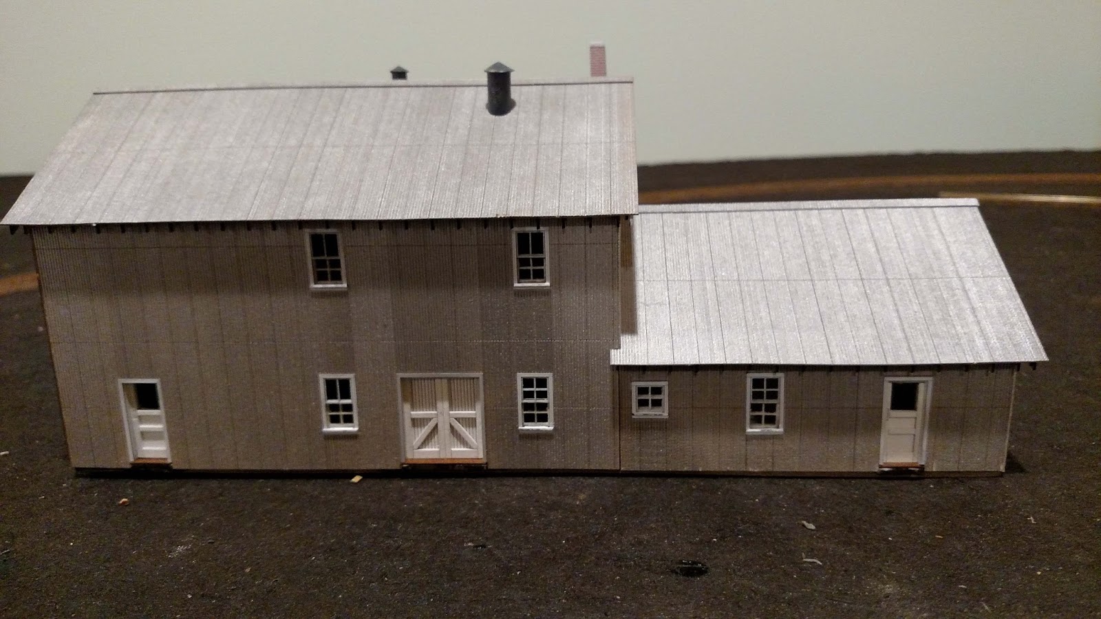
Three of the four outbuildings for my Vance Junction scene have been completed, with the converted passenger car remaining to be finished.  These buildings were built from Banta Modelworks kits, and finished similarly to the Vance Junction Section House previously described.  The roofs on all of these buildings are tarpaper, and were painted with my dwindling supply of Polly Scale Grimy Black.  These buildings are located on the hillside adjacent to the Section House.
The handcar shed and boxcar shed at Vance Junction.  This is the trackside view of these buildings.

The shed and lean-to at Vance Junction.  The disks serve to hold the building in position until the model is permanently installed at Vance Junction.  This is the rear, non-trackside view of the building.

Vance Junction Section House

I recently completed the Vance Junction Section House.  This building was built from a Banta Modelworks kit, and went together very well.  The building is painted using Star brand paints, available from P-B-L.  The colors used were Jersey Cream for the body of the building, with D&RGW Trim Brown for the trim.  The basement board-and-batten siding was stained with Hunterline Barn Red stain, and the weathered wood deck and railings were stained using Hunterline Creosote Black.

Rear view of the Vance Junction Section House.  

Rear 3/4 view of the Vance Junction Section House.

Front (trackside) view of the Vance Junction Section House.


Scatter Grip, the adhesive I used to attach the laser-cut shingles to the roof.  This adhesive is brushed onto the roof surface, and stays sticky for weeks.  This allows plenty of time to attach the shingles without concern that the adhesive will dry out before the shingling is completed.

Thursday, July 22, 2021

Telluride Branch and Pandora

I have recently completed the Telluride Branch of the Rio Grande Southern Railroad, including the Pandora mining area.  The track plan for Telluride and Pandora was designed using Mike Blazek's Telluride and Pandora workbooks.

As with the rest of the layout, the track consists of Micro-Engineering Code 55 Flex Track.  There are 22 turnouts in Telluride and Pandora, all of which are handlaid using FastTracks fixtures.  Two of the turnouts are curved turnouts custom built to fit on the curves entering Pandora.

The turnouts are controlled, as on the rest of the layout, by Tortoise by Circuitron slow-motion switch machines.  Berrett Hill Easy Wire Tortoise Adapters ( click here) are used to simplify wiring.  Fascia-mounted Berrett Hill Touch Toggles are used for control.  

Wiring has been completed, and will be the subject of an additional post.  UTP panels have been installed in the fasica, although the layout is equipped with radio throttles.

A swing gate was installed across the bathroom doorway to connect Telluride to the rest of the layout, while still allowing access to the bathroom.  This will be the subject of a future post as well.

Overall view of Telluride.  Note the Raggs....to Riches Telluride depot.  The first train, headed by RGS  455 is leaving town.

The first train from Telluride is crossing the double deck swing gate .

The first train from Telluride is now leaving the swing gate, and is descending Keystone Hill, which on my layout is located above Placeville.


Saturday, January 23, 2021

Wye Turnout Control for the Telluride Branch

 Sometimes a small piece of technology comes along that makes operating your model railroad just a bit easier, or a bit more intuitive.  The Wye Track Adapter, from Berrett Hill Trains (http://www.berretthillshop.com/store/products/wye-adapter/) is just such a piece of technology.  I recently installed a Wye Track Adapter to control the turnouts of the wye (of course!) located between Telluride and Pandora on the Telluride Branch of my RGS layout.

The concept behind the Wye Track Adapter (WTA) is to use Touch Toggles to select a route through the wye, rather than selecting individual turnouts.  Some of my operators have experienced confusion setting the individual turnouts in a wye to the route that they wish to travel, especially if one of the turnouts is in a location where it is difficult to see which way the turnout is thrown.

I have installed the Touch Toggles into a small temporary control panel (as a 'proof-of-concept') mounted on the fascia.  The Touch Toggles are mounted such that the toggle itself is located between the turnouts.  The red or green indication on the toggle shows whether the turnouts are aligned for the route:  if the toggle is green, the two turnouts are aligned to allow train passage along the route.  The operator must only touch the toggle for the route desired.

So, how does one install such a beast?  Installation is actually simple, but a couple of notes may be helpful to you if you choose to install the WTA.


The Wye Track Adapter installed to the benchwork and connected to the two left inputs on the Direct Base.

The above photo shows the Wye Turnout Adapter plugged into the Direct Base.  The following steps should help clarify the installation:

1.  Note that the far left output (the blue connector at the top of the Direct Base) is wired to two Tortoise switch machines.  These will be thrown simultaneously.

2.  Temporarily plug a Touch Toggle into the far left input on the Direct Base.  This Toggle will throw the two turnouts for the main route simultaneously.

3.  Adjust the wiring to the two Tortoises so that both turnouts are aligned for the main route when the left Touch Toggle is green.

4.  Temporarily plug a Touch Toggle into the input next to the far left input.  Adjust the wiring such that the turnout is thrown in the proper direction.

5.  Disconnect the two Touch Toggles.

6.  Plug the WTA into the two inputs.

7.  Plug the Touch Toggle corresponding to the default route into Position 1 on the WTA.

8.  Plug the Touch Toggle selecting the second route into Position 2 on the WTA.

9.  Plug the third Touch Toggle onto Position 3 on the WTA.

10.  Note that the third input and output from the left will not be used.

Temporary track diagram of the wye located between Telluride and Pandora.  The green light indicates the selected route, with both turnouts aligned for this route

So, you may ask:  "Do you recommend the Wye Track Adapter?"   Yes, I do.  When properly installed, the selection of the route through the wye is intuitive, even to neophyte operators, and the turnouts for the through route are automatically aligned upon powering up the layout.  Try it - you'll like it!


Thursday, October 8, 2020

Updated "Final" Track Plan


There is, apparently, no such thing as "final"!  I have updated the track plan to show the additional industries that I recently added to Durango.  I added five sidings:  a siding for the Graden Flour Mill, the Federal Lumber Company, a Machinery Sales Company, the Conoco Oil Platform, and the Telluride Iron Works.  These tracks and industries are installed and functional.  This should allow for more challenging operations for the Durango operator.

"Final" Rio Grande Southern Railroad track plan, with additional industries located in Durango.


Wednesday, May 20, 2020

Ophir General Merchandise

I recently completed my model of the Ophir General Merchandise kit by Banta Modelworks (https://www.bantamodelworks.com/).  This kit was a challenge to bring to completion owing to a lack of information in the kit regarding the arrangement of the railings, stairways, and ladders on the decks and catwalks.  However, I made use of Mike Blazek's plans (http://blazeksplan.com/) for the structure, photos from the Rio Grande Southern Story, and parts from my scrap box to complete it.  I also found an adhesive which makes installation of the non-peel-and-stick shingles included in the kit much easier.


The Ophir General Merchandise store in HO scale.  This front view shows the gas pump from my scrap box, and the 3/4" thick pine block glued to the underside of the front porch to eliminate a warp.  The building is located adjacent to the track, with a road to the left climbing a steep grade.  The ladder, catwalk, and stairway shown in front of the building will be installed after the building is installed on the layout.
The left side of the Ophir General Merchandise.  The catwalk will be located between the second story doorway and the roadway.  The stairway leads down from the road to the front porch.


The right side of the Ophir General Merchandise, showing the tarpaper siding and basement wall.  The building is located on a sloped site, so the block in front will be hidden,

The rear of the Ophir General Merchandise.  The platform on the right will be accessed by the ladder (on the left).


Scatter Grip, the adhesive I used to attach the non-peel-and-stick shingles.  The material is painted onto the surface and allowed to dry.  It remains tacky for hours, so there is ample time to complete installation of the strips of shingles.  I found this to be much less frustrating and annoying than attempting to use spray glue to attach the shingles.  The product is available from Amazon.  Search for Deluxe Materials Scatter Grip.


Rio Grande Southern T-19 Number 20


I recently added an additional Rio Grande Southern locomotive to the roster.  I purchased this locomotive a Precision Scale T-19, back in 2014 at the National Narrow Gauge Convention in Overland Park, Kansas.  I added a Soundtraxx Tsunami-2 Steam Decoder, the TSU-1100, a Soundtraxx Currentkeeper, and a Mini Cube speaker.  All of this equipment fit into the small tender!  The headlight is illuminated with an LED made by Evan Designs (www.ModelTrainSoftware.com).  This LED operates on 7-19 volts AC, DC, or DCC.  It includes a tiny bridge rectifier, which I was able to install in the smokebox.  The leads are simply soldered to the F0 function leads from the decoder, which are the white and blue wires.  There was no need to calculate the size of resistor necessary, as it is included with the LED.  I added window glass, painted the tires, axle ends, and journal boxes a weathered white, and installed a coal load made from real crushed and sized narrow gauge coal.


The Rio Grande Southern T-19 Number 20.  


Sunday, May 17, 2020

Electrical Plan for the Rio Grande Southern

Attached is the electrical plan for the Rio Grande Southern railroad.  This diagram shows each of the power districts, reversing sections, and the programming track.  The railroad uses the main NCE Power Pro command station, two NCE Boosters, eight PSX circuit breakers, three PSX-AR auto-reversers, and three OG-AR auto-reversers.  The Ridgway, Telluride, and Pandora portions of the layout have not yet been constructed, so the electrical components for these towns are not in place.


Wednesday, April 29, 2020

Booster for the Rio Grande Southern

I recently added a booster to the layout to provide additional power, and resiliency during operating sessions.  I added an NCE Power Pro PB5 booster, and two additional PSX-1 circuit breakers.  The result of this enhancement is that the long power district supplying power to Dolores, Rico, Ophir, Vance Junction, Vanadium, and Placerville is now three separate districts.  Dolores is on the original district, while Rico and Ophir are within their own district.  Vance Junction, Vanadium, and Placerville are also a separate district.  The advantage of providing the additional districts is that, for example. a derailment/short circuit in Dolores will not cause the operators in Rico to lose functionality.

A note on the installation of the PB5 booster would be appropriate.  This booster is located beneath Ophir, about 40 feet from the Power Pro Command Station located under Durango.  This necessitated adding a control bus between the Command Station and the Booster.  I confirmed with NCE that the control bus can be up to 300 feet long, so 40 feet is not a problem.  Additionally, I confirmed with NCE that a floating ground should be connected between the Command Station and the Booster.  I used 16 gauge wire, and ran it from a case screw on the Command Station to a case screw on the Booster.

An interesting note on the effectiveness on the floating ground:  When I first installed the Booster, I tested the installation without the floating ground between the Command Station and the Booster.  All worked well, with a smooth transition of the locomotive from the Rico power district to the Dolores power district.  I thought, "Great!  I had a 50% chance of connecting the track wires in proper phase, and I got it right!"  I immediately completed the installation of the floating ground, test ran the locomotive from the Rico district into the Dolores district, and had a short circuit, indicating that the polarity of the rails was reversed.  I reversed the track feed from the Booster to the PSX circuit breakers, and now the polarity is correct, with a smooth transition from the Rico district to the Dolores district.

My recommendation is to be sure to install the floating ground between the Command Station and the Booster.  Incidentally, no mention is made of the need for a floating ground in the instructions that came with the Booster.

NCE Booster installed under Ophir.  The track power goes to the PSX Circuit Breakers, the control bus connects the Command Station to the Booster, and the floating ground at the rear of the Booster connects to the case of the Command Station.

PSX Circuit breakers installed under Ophir.


Thursday, April 2, 2020

Final Track Plan

I have completed the final track plan for the Rio Grande Southern Railroad in HOn3!  Note that Ridgway has been moved into the adjacent room, and that the Enterprise Branch and Telluride Branch are now included for additional operating interest.

The Enterprise Branch is physically located above the town of Dolores, with a connection to the town of Rico.  This branch will be operated by a Shay locomotive, and has several mines, which have been relocated from my previous layout.  The Enterprise Branch is freelanced, although it is based upon the prototype Enterprise Branch.

Ridgway, Telluride, and Pandora follow the prototype track plans, although they are compressed, as always seems to be required!  We never have all the space we want for our railroads!

Trains are currently operating through Placerville, with the end-of-track at the far end of Placerville.  I anticipate beginning benchwork construction of the new portion of the layout within the next week.

The Rio Grande Southern Railroad, as modeled in HOn3.  This is the final version of the trackplan.

Wednesday, June 20, 2018

Telluride Coal for Rico

I recently completed the Telluride Coal facility for my town of Rico, CO.  This is one of the buildings included in Banta Modelworks new kit, Rico Outbuildings.  This kit was a very easy build!  I prestained all parts using Hunterline Creosote, which has become my "go-to" stain for aged timbers.


Telluride Coal at its location in Rico., near the Pro Patria Mill.  The building needs to be "dirted in".  The vehicle is a Classic Model Works Chevrolet pickup

A front view of the Telluride Coal facility in Rico.

A side view of the Telluride Coal facility.  The Pro Patria Mill is in the background.

Wednesday, June 6, 2018

Dedicated Programming Track


This is my first post in quite a while.  The past several months have been quite busy!  I was recently married to a lovely woman, Patty, that I have been seeing over the past year, and model railroading, particularly updating my blog, has not been high on my priority list!

Patty and I dancing the Waltz at our favorite local winery, South Creek Vineyards.


Having said that, my wife Patty is supportive of my hobby/passion, and will be going to the upcoming Narrow Gauge Convention in Minneapolis-St. Paul in September!

One of the items that I accomplished recently was installing a dedicated programming track on my layout.  This is the first dedicated programming track that I have had, and it was well worth figuring out how to incorporate such an item into my layout.  This track is an existing track servicing the turntable, and was particularly suited because it had already been isolated from adjacent tracks, as they were part of the reversing loop on the layout.  The following electrical diagram of the Durango Yard portion of my railroad will illustrate the location of the programming track.
Figure 1.  Electrical diagram of the Durango Yard.  The green tracks are District 1; the blue tracks are District 2; and the red tracks are the reversing section, controlled by a DCC Specialties OG-AR circuit board.  The Purple track is the programming track.

Figure 2.  Detailed view of the Durango Yard showing the location of the Programming Track (in purple), the reversing section (in red), and District 1 (in green).  
The programming track is electrically isolated from the rest of the layout by gaps in both rails where it joins the turnout in the reversing section.  Obviously, the track is gapped at the turntable!  The track is fed trough a DPDT electrical switch mounted on the layout fascia,  In one position, the track acts simply as a normal section of trackage; in the "Programming" position, the track is a dedicated programming track.  I chose this track as it is near the location of my NCE DCC system, and that simplified wiring.  Also, because I use JMRI Decoder Pro to program my decoders, I wanted the Program track to be near the DCC system and my laptop computer.


Thursday, September 21, 2017

The Dolores Feed and Flour Mill

I recently purchased a kit for the Dolores Feed and Flour Mill produced by Narrow Gauge Colorado.  I have completed its construction, and wanted to share my experience regarding it construction, fit of parts, and instructions.

The kit consists of laser-cut parts that fit together perfectly.  The kit consists of laser-board sub walls, to which one glues the laser cut (perhaps laser-sculpted would be a better descriptor) corrugated siding.  The roof stacks appear to be 3-D printed parts, and fit into the pre-cut holes in the roof panels perfectly.  Kudos to the individual who did the laser cutting and 3-D printing.

 Because the instructions are rather short on detail, I have put together the following assembly sequence which I used to assemble this kit.  Follow along as I describe how I completed the Feed and Flour Mill.

1.  Assemble the subwalls, ensuring that the parts are aligned accurately.  I assembled the walls using Loctite thin ACC for the entire project.
2.  Paint the doors, assemble them, and glue to the backs of the subwalls, centering them in the openings.  I painted the doors using Rust-O-Leum's Clean Metal Primer, which is a nice white color.  I aligned the doors in their openings such that a space was left at the bottom to allow for the sills.
3.  Glue the floor and subfloor together, again using the Loctite ACC.  Ensure that the round holes in the floor are in alignment.
4.  Glue the back subwall to the base, ensuring that it is square to the base.
5.  Glue the second floor to the rear subwall, ensuring that it is square to the subwall.
6.  Glue the two-story gable subwall to the floor, second floor, and rear subwall.
7.  Glue the interior two-story gable subwall to the floor, second floor, and rear subwall.
8.  Glue the single-story gable subwall to the floor, and rear subwall.
9.  Glue the front subwall to the floor, second floor, and all three gable subwalls.
10.  Paint the siding and the roof your favorite shade of silver to represent galvanized metal.  I used Star-brand Smokebox Silver for the walls, and Floquil Platinum Mist for the roof panels.
11.  When thoroughly dry, mask the walls using blue painter's tape, exposing the windows and door trim.  These details are laser-cut into the corrugated siding.  I painted the windows and doors with Model Master White.
12.  Add the glazing to the windows using Canopy Glue.  Note that the glazing is to be installed on the outside and inside of the of the subwalls.  Recessed areas are laser-cut into the front surface of the subwalls to receive the glazing.

13.  Glue the front and rear siding to the subwalls, using Loctite ACC.  Then glue the two ends to the assembly, also using Loctite ACC.
15.  Install all roof rafters, and rafter tails into the slots in the completed walls.
16.  Add the subroof panels to the single-story portion of the structure ONLY.
17.  Glue the final piece of siding to the gable subwall above the subroof panel, using the Loctite ACC.
18.  Add the subroof panels to the two-story portion of the structure, again using the Loctite ACC.
19.  Add the notched rafters and barge boards to the roof, and paint them the trim color.
20.  Pre-paint the window sills the trim color, and install all window and door sills.
21.  Add the corrugated roof panels to the subroof.  I used Aleene's Tacky Glue to allow positioning.
22.  Add the corrugated ridge strips to the roofs.
23.  I weathered the Mill with Pan Pastels.  I used the following colors to achieve a rusty, weathered appearance:  Neutral Gray Shade; Burnt Sienna Shade; and Red Iron Oxide.
24.  I installed the structure in my town of Dolores, where it is ready to receive shipments!


The Dolores Feed Mill showing the painted and installed doors.

The front two-story wall of the Dolores Feed Mill, showing the fine laser-cut corrugations.  Note the Painted window and door trim.


The completed Dolores Feed Mill, prior to weathering.

Another view of the completed Dolores Feed Mill prior to weathering.

Three-quarter view of the Mill, showing the laser-cut wood end wall.

The rear of the Dolores Feed Mill.

The Dolores Feed and Flour Mill in place on the layout.

Wednesday, June 14, 2017

Operations on the Rio Grande Southern

Now that trackwork has been completed from Durango though Rico to Ophir, I have begun to host operating sessions on the railroad.  While the first two sessions were a "shakedown cruise" for the railroad, I decided that for the latest session I would initiate a trial operating session using card cards and waybills.  I used this system on my previous layout, and liked it.

In this session, I simply recycled the car cards and waybills from the old layout, and made some minor changes to adapt them to the current layout.  I also needed a place to store the car cards, so I made car card boxes and attached them to the fascia in each location where switching was to occur.  I made the car card boxes from nominal 1/4" lauan plywood.  Similar boxes are commercially available from Micro-Mark, but I wanted to customize the sizes to fit my operating scheme.

The following photos illustrate the basic construction of these boxes.  The boxes will be painted green to match the color of my fascia.


These are the parts required to construct a single box, with a coupler pick holder on one side.  The back is 3 1/2" tall, by 2 1/4" wide; the front is 1 3/4" by 2 1/4".  the bottom and side pieces are each 1/2" wide, with the bottom being 2/14" long.  The two side pieces are cut to fit, but will be approximately 1 1/2" tall.


These are the parts for a double box.  The parts are all the same size as for the single box, but are 4 1/2" long.


This is a completed triple box.  This box is 7 3/4" wide.  The attached coupler pick holder is approximately 1" square:  I cut it on my table saw to exactly match the thickness of the completed box.

Monday, March 27, 2017

Spline roadbed

I am starting the trackwork to Ophir following the completion of trackwork in Rico.  I am trying out a new technique to make the spline roadbed.  This was suggested to me via email from Steve Hatch, of Railway Engineering.  This method is faster to construct, and I find that it is easier for me to keep the splines and blocks aligned crossways than in the method I used before.

As before, I cut splines from scrap lauan plywood.  I cut the strips 3/4" wide, rather than 1/2" as I did previously.  The thicker splines were chosen to match up with the 3/4" plywood base used for Rico.  I then squared up a piece of leftover 2"x2" pine, as used for legs on the layout, such that it was exactly 1.5" square.  The legs were carefully crosscut on my table saw into pieces 3/4" long.  These were laminated between the two 3/4" splines, and glued in place with Titebond III Ultimate Wood Glue.  This glue is waterproof, which is an important consideration, since delamination of the roadbed while installing scenery would not be a good thing!  The width of the completed spline roadbed is an exact match for the Cascade Rail Supply milled Homasote roadbed.  It still requires a lot of clamps to construct the roadbed!


Initial installation of the spline roadbed.  The outside spline was simply clamped to the existing 3/4" plywood roadbed.  The roadbed will be trimmed, and aligned with the track centerline.


The spline roadbed with about half of the spacer blocks glued in place.


Question:  How many clamps does it take to build spline roadbed?  Answer:  All of them!

A closeup view of the spline roadbed.  The roadbed will be sanded smooth prior to installation of the Cascade Rail Supply milled Homasote roadbed.

A closer view of the completed spline roadbed.

The spline roadbed sanded and with the track centerline marked.  The milled Homasote roadbed will be installed using the marked centerline. 

Tuesday, March 21, 2017

On To Rico

I have just completed laying track into Rico on my version of the Rio Grande Southern Railroad.  The majority of the trackwork was fitted onto a piece of 3/4" plywood 12 1/2 inches wide by 8 feet long.  Adjacent to this is my version of the Pro Patria Mill.  This was scratchbuilt by me, and resided on my previous layout.  Fortunately, I was able to relocate it to my new home, and I completed the model with the addition of the truck dump, and associated support structures.

As with the rest of the layout, the trackwork consists of Micro Engineering Code 55 Flex Track.  I scratchbuilt the nine turnouts using Fast Tracks fixtures.  All turnouts are Number 6.  One turnout, behind the depot, will connect the Enterprise Branch to Rico.  I anticipate much operating potential arising from the inclusion of the Enterprise Branch.  All trackwork is installed onto Cascade Rail Supply Homasote Roadbed.  All turnouts are powered by Tortoise switch machines, and are controlled by Berrett Hill Trains Touch Toggles.

 Because of space constraints, my version of Rico does not include the engine servicing facilities located at the prototype.  However, I believe that the flavor of Rico is captured, and much operation should be possible at this location.  I will be interested to see how the scale track works into the operating scheme!

Next up:  Ophir!


The first train to Rico leaving the Coke Ovens and approaching Rico.  The 3/4" plywood roadbed is clearly seen.

The East end of Rico.  The yellow building to the left is the scale house, which has its own track.

The Pro Patria Mill at the West end of Rico.


An overall view of the town of Rico.  The station under construction is a Raggs...to Riches kit.  I built it to this stage in order to check clearances within Rico.


The first train to Rico, powered by RGS 461, enters Rico.  The locomotive is a Blackstone Models K-27.


The train is stopped at the Rico station.


Mudhen 461 is on the mainline headed toward what will be Ophir.


Mudhen 461 is on the siding which will service the Rico Power and Light facility, and a commercial coal bin.